5 Minutes Read
Unified Diagnostic Services (UDS), defined by ISO 14229, is the globally accepted diagnostic communication protocol used by automotive OEMs and Tier-1 suppliers to communicate with vehicle Electronic Control Units (ECUs). First published in 2006 and last revised in 2020, ISO 14229 has become the diagnostic foundation for every modern vehicle platform, from passenger cars and commercial vehicles to electric vehicles (EVs) and Software-Defined Vehicles (SDVs). Modern vehicles contain 70 to 100 ECUs. As vehicles become software-defined, UDS is no longer just a service tool protocol; it is the diagnostic backbone for ECU development, End-of-Line (EOL) manufacturing testing, field service, over-the-air (OTA) firmware updates, and post-production cybersecurity monitoring mandated under India’s AIS-189.
This guide covers everything engineers and OEM program teams need to understand about UDS: how it works, all key service identifiers (SIDs), Negative Response Codes (NRCs), security architecture, flash programming, Data Identifiers (DIDs), AUTOSAR integration, and how UDS is evolving for EV and SDV platforms.
What Is UDS (ISO 14229)?
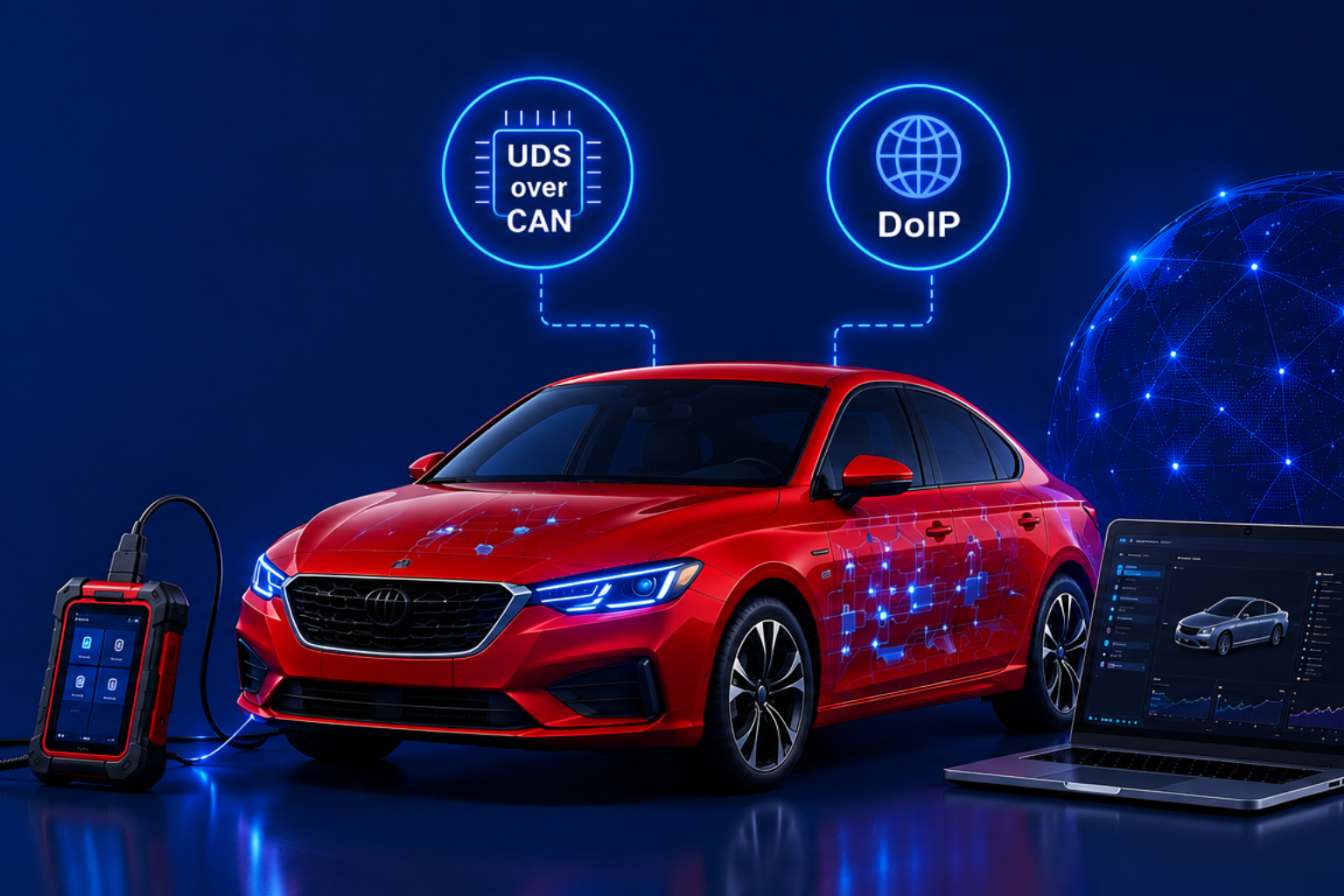
UDS (Unified Diagnostic Services) is an application-layer diagnostic protocol defined by ISO 14229 that enables a diagnostic client (tester, scan tool, OTA server, or EOL tester) to communicate with ECUs (servers) in a standardised, manufacturer-independent manner. UDS evolved from ISO 14230 (KWP2000) and ISO 15765, consolidating previously fragmented, manufacturer-specific diagnostic protocols into a single universal framework. UDS is data-link independent: it operates over Classical CAN and CAN-FD via ISO-TP (ISO 15765-2), over Automotive Ethernet via DoIP (ISO 13400), over LIN (ISO 17987), and over FlexRay (ISO 17458), making it applicable across all major automotive network architectures.
Using UDS (ISO 14229), diagnostic clients can:
- 0x19 – Read and clear DTCs: retrieve active, stored, and pending Diagnostic Trouble Codes with status and freeze-frame data
- 0x22 – Read live ECU data: access real-time parameters via Data Identifiers (DIDs)
- 0x2E – Write ECU parameters: configure calibration values or enable/disable features via DID
- 0x31 – Execute routines: trigger EOL tests, actuator checks, and diagnostic procedures
- 0x27 – Authenticate secure operations: unlock protected sessions via seed-key exchange
- 0x34/0x36/0x37 – Update ECU software: initiate, transfer, and exit firmware download sequences
UDS vs OBD: UDS (ISO 14229) and OBD-II (SAE J1979) serve different purposes. OBD-II is a regulatory standard governing emission-related diagnostics accessible through the standard OBD port. UDS is an engineering protocol governing all ECU diagnostic functions. As of SAE J1979-2 (OBDonUDS), OBD emissions diagnostics will run on top of the UDS architecture from 2027 onwards for US market vehicles. ElectRay’s OBDonUDS Stack implements this convergence.
ElectRay’s UDS Stack is a production-grade, AUTOSAR-aligned ISO 14229 implementation supporting CAN, CAN-FD, and DoIP transport layers, deployed in production programs across passenger EVs, commercial vehicles, and motorcycles.
How Does UDS Work?
UDS follows a Client-Server model. The diagnostic client sends a service request to the ECU server. The ECU validates the request against the current diagnostic session, security level, and ECU state, then returns either a Positive Response (Service ID + 0x40, followed by response data) or a Negative Response (0x7F + original SID + Negative Response Code). Positive responses carry the SID offset by 0x40: a successful 0x22 RDBI request returns 0x62. A failed request returns 0x7F followed by the original SID and the NRC byte identifying why the request was rejected.
UDS Across the ECU Lifecycle
UDS is not limited to workshop diagnostics. It plays a critical role throughout the complete ECU lifecycle, from initial hardware bring-up to post-production vehicle support. As vehicles become increasingly software-defined, the importance of UDS extends well beyond fault code reading into manufacturing, OTA updates, cybersecurity, and fleet operations.
| ECU Lifecycle Stage | How UDS Is Used |
|---|---|
| ECU Bring-up | Hardware validation, memory verification, peripheral testing and initial software download |
| Software Development | Live parameter monitoring, routine execution, debugging and ECU configuration |
| Calibration & Validation | Reading sensor data, writing calibration parameters, actuator testing and verification |
| End-of-Line (EOL) Manufacturing | ECU flashing, VIN programming, production diagnostics and quality validation |
| Vehicle Service | Reading and clearing DTCs, live diagnostics, ECU replacement and software updates |
| OTA Updates | Secure firmware download, programming session management, integrity verification and rollback protection |
| Fleet Operations | Remote diagnostics, predictive maintenance, software health monitoring and warranty analytics |
| End-of-Life Analysis | Failure investigation, software traceability and field issue root-cause analysis |
This broad lifecycle coverage is one of the reasons UDS has remained the industry’s dominant diagnostic protocol for nearly two decades. Rather than being a workshop protocol, UDS has evolved into a foundational software service used across development, production, service, and connected vehicle operations.
Diagnostic Sessions
UDS controls service availability through diagnostic sessions, switched using service 0x10 (DiagnosticSessionControl):
- Default Session (0x01): basic diagnostics only; available immediately at ECU power-on
- Extended Diagnostic Session (0x03): advanced diagnostics, configuration, and routine control; used during development and service
- Programming Session (0x02): ECU software flashing and bootloader operations; access restricted by security access
TesterPresent (0x3E)
When a non-default session is active, the ECU will time out and revert to Default Session if no request is received within the session timeout window (typically S3server = 5 seconds). The TesterPresent service (0x3E) is sent periodically by the client to keep the session alive during long operations such as multi-block firmware transfers.
UDS Service Identifiers (SIDs): Complete Reference
The following table lists all major UDS Service Identifiers (SIDs) defined in ISO 14229. This is the complete reference engineers use when implementing, configuring, or debugging UDS diagnostic sessions. Each SID is the first byte of every UDS request message.
| SID | Service Name | Primary Use |
|---|---|---|
| 0x10 | DiagnosticSessionControl | Switch between Default, Extended, and Programming sessions |
| 0x11 | ECUReset | Trigger hard, soft, or key-off ECU reset |
| 0x14 | ClearDiagnosticInformation | Clear stored DTCs and associated data from ECU memory |
| 0x19 | ReadDTCInformation | Read active, stored, and pending DTCs with status and freeze-frame data |
| 0x22 | ReadDataByIdentifier (RDBI) | Read live ECU parameters via Data Identifier (DID) |
| 0x27 | SecurityAccess | Seed-key authentication for protected diagnostic operations |
| 0x28 | CommunicationControl | Enable or disable ECU network communication during diagnostics |
| 0x2E | WriteDataByIdentifier (WDBI) | Write configuration or calibration data to ECU via DID |
| 0x31 | RoutineControl | Start, stop, or query ECU diagnostic routines (e.g. EOL tests, actuator checks) |
| 0x34 | RequestDownload | Initiate firmware download to ECU memory |
| 0x36 | TransferData | Transfer firmware blocks during download or upload |
| 0x37 | RequestTransferExit | Terminate data transfer and trigger integrity check |
| 0x3E | TesterPresent | Keep non-default diagnostic session alive during long operations |
| 0x85 | ControlDTCSetting | Enable or disable DTC recording during programming or EOL testing |
| 0x86 | ResponseOnEvent (ROE) | Configure ECU to send unsolicited responses when specific events occur |
Data Identifiers (DIDs): Reading and Writing ECU Parameters
A Data Identifier (DID) is a two-byte identifier used by UDS services 0x22 (ReadDataByIdentifier) and 0x2E (WriteDataByIdentifier) to reference specific ECU parameters. DIDs are the primary mechanism through which diagnostic tools access live data, ECU configuration, calibration values, and vehicle identification information.
DIDs are structured in three categories:
- Standardised DIDs (ISO 14229): defined by the standard and identical across all OEMs. Examples include 0xF186 (ActiveDiagnosticSession), 0xF18B (ECUManufacturingDate), 0xF18C (ECUSerialNumber), 0xF190 (VehicleIdentificationNumber), 0xF195 (SystemSupplierECUSoftwareVersionNumber)
- OEM-specific DIDs: defined by the OEM in a vehicle-specific diagnostic database (ODX/DEXT file). These cover proprietary calibration values, feature flags, SoC/SoH parameters for BMS ECUs, and production configuration data
- Supplier-specific DIDs: defined by the ECU supplier for component-level diagnostics not covered by OEM DIDs
For EV platforms, BMS and OBC ECUs carry ZEVonUDS DIDs defined under SAE J1979-3, covering battery State of Health (SoH), State of Charge (SoC), cell temperature distribution, isolation resistance, and charging session parameters. These EV-specific DIDs are not covered by ISO 14229 and require the ZEVonUDS extension.
ElectRay’s ZEVonUDS Stack implements SAE J1979-3-aligned EV-specific DIDs for BMS, OBC, thermal management, and motor controller ECUs, extending the ISO 14229 framework for full EV diagnostic coverage.
Security Access (0x27): Protecting Critical ECU Functions
Not every diagnostic operation should be available to every user or tool. UDS implements Security Access (Service 0x27) using a seed-key authentication mechanism to gate access to programming sessions, calibration writes, and other security-sensitive operations.
The security access sequence:
- Client sends 0x27 requestSeed (sub-function 0x01 or odd sub-function value)
- ECU generates a random seed value and returns it in the positive response
- Client calculates the corresponding key using the OEM-specific algorithm
- Client sends 0x27 sendKey (sub-function 0x02 or even sub-function value)
- ECU validates the key and grants access to protected services if correct
Security Levels
Most production ECUs implement multiple security levels rather than a single unlock mechanism. Different security levels grant access to different categories of protected services. For example, one level may permit calibration updates, another may enable manufacturing operations, while a higher level is reserved for bootloader programming or OEM engineering functions. This layered approach follows the principle of least privilege, ensuring that diagnostic tools receive only the level of access necessary for their intended purpose.
Production-grade implementation requires HSM (Hardware Security Module) execution of the seed-key algorithm. Running the algorithm in application software exposes the key derivation logic to reverse engineering. The HSM isolates cryptographic operations in hardware, preventing key extraction even if the ECU’s main application is compromised. This is mandated by AIS-189 and ISO/SAE 21434 for vehicles requiring CSMS compliance.
Brute-force protection is also mandatory: ISO 14229 requires ECUs to implement a lockout mechanism (NRC 0x36: exceededNumberOfAttempts) that activates after a configurable number of failed key attempts and enforces a delay timer before further attempts are permitted. This prevents automated key brute-forcing through the diagnostic interface.
ECU Flash Programming over UDS
ECU software flashing via UDS is the most security-sensitive and operationally critical diagnostic function. The standardised UDS programming sequence, used in production End-of-Line flashing, workshop reprogramming, and OTA update pipelines, follows this order:
- Step 1: Switch to Programming Session (0x10, sub-function 0x02)
- Step 2: Perform Security Access (0x27) to unlock programming functions
- Step 3: Disable DTC recording (0x85) and communication control (0x28) to prevent interference
- Step 4: Send RequestDownload (0x34) specifying memory address, size, and compression/encryption format
- Step 5: Transfer firmware blocks using TransferData (0x36), each block verified by sequence counter
- Step 6: Send RequestTransferExit (0x37) to terminate transfer and trigger integrity check
- Step 7: Execute CheckMemory routine (0x31) to verify CRC or hash of written firmware
- Step 8: ECU Reset (0x11) to boot into new firmware
Production-grade flash programming requires two additional mechanisms not in the original blog. First, A/B partition management: new firmware is written to an inactive memory partition while the ECU continues running on the current firmware; the partition switch occurs only after the integrity check passes, eliminating the risk of a bricked ECU mid-update. Second, anti-rollback protection: a firmware version counter stored in protected Non-Volatile Memory (NVM) prevents downgrade to older firmware versions with known vulnerabilities. Both are required by AIS-190 for OTA-capable ECUs.
Secure Boot Completes the Software Update Chain
While the Flash Bootloader ensures that firmware is transferred and programmed correctly, Secure Boot verifies the authenticity and integrity of the firmware every time the ECU powers up. Together, secure flashing and Secure Boot establish a complete chain of trust, ensuring that only authenticated and untampered software is executed throughout the ECU lifecycle. This architecture is increasingly expected for vehicles complying with AIS-189, AIS-190, ISO/SAE 21434, and UNECE R155.
ElectRay’s FBL Secure Flash Bootloader implements the full UDS programming sequence with A/B partition management, HSM-backed signature verification, anti-rollback counters, RAM-resident flash driver, and AIS-189/AIS-190-aligned security, deployed in production programs.
Negative Response Codes (NRCs): What They Mean
When an ECU cannot process a UDS request, it returns a Negative Response structured as: 0x7F (Negative Response SID) + original SID + NRC byte. NRCs tell the diagnostic client precisely why a request was rejected. Six NRCs account for the majority of issues engineers encounter during UDS development, integration testing, and field diagnostics:
| NRC | Name | Common Cause |
|---|---|---|
| 0x22 | conditionsNotCorrect | ECU pre-conditions not met: wrong session, vehicle speed non-zero, or required prior service not executed |
| 0x31 | requestOutOfRange | DID or routine identifier not supported, or parameter value outside the permitted range in the active session |
| 0x33 | securityAccessDenied | Attempted a protected service without first unlocking via Security Access (0x27) |
| 0x35 | invalidKey | Seed-key mismatch: wrong key calculated or sent in response to the ECU seed |
| 0x36 | exceededNumberOfAttempts | Too many failed Security Access attempts; ECU lockout timer activated. Wait for delay before retrying |
| 0x78 | responsePending (not an error) | ECU received the request correctly but needs more processing time. Final response follows after operation completes. Common during erase and verification in programming sessions |
The complete ISO 14229 NRC reference covers codes from 0x10 through 0xFE, including OEM-reserved ranges (0x80-0xFF). For a full NRC reference table covering all standard and commonly used OEM-specific codes, refer to the ElectRay UDS Diagnostics Reference on our website.
UDS in AUTOSAR: DCM, DEM, and ODX
In AUTOSAR Classic architecture, UDS is implemented through a stack of standardised software components:
- DCM (Diagnostic Communication Manager): handles UDS service processing, session management, security access, and request routing to application software
- DEM (Diagnostic Event Manager): manages DTC storage, DTC status byte, freeze-frame data, and event memory
- CanTp / DoIP: transport layer handling ISO-TP segmentation over CAN or TCP/IP encapsulation over Ethernet
- NvM (Non-Volatile Memory Manager): persistent storage of DTCs, freeze frames, and calibration data
- ODX (Open Diagnostic data eXchange, ISO 22901): the data format standard that describes all DIDs, DTCs, service configurations, and session definitions in a portable, tool-independent XML structure. ODX files are the single source of truth for a vehicle's diagnostic database, used by ECU development tools, production testers, and workshop scan tools
- SOVD (Service-Oriented Vehicle Diagnostics): the next-generation diagnostic framework for AUTOSAR Adaptive platforms, SOVD complements rather than immediately replaces UDS and is expected to coexist with UDS throughout the SDV transition, particularly as AUTOSAR Classic and Adaptive platforms operate together within the same vehicle. SOVD enables cloud-native diagnostic integration and is gaining adoption in SDV programs targeting zonal E/E architectures
ElectRay's UDS Stack is fully integrated with AUTOSAR DCM and DEM, supports ODX 2.2.0 import for automatic DID and DTC configuration, and provides a migration path to SOVD for AUTOSAR Adaptive programs.
UDS in Modern SDV Architectures
Software-Defined Vehicles (SDVs) are changing the underlying communication architecture, but not the diagnostic language itself. UDS (ISO 14229) continues to be the application-layer diagnostic protocol; what changes is the transport mechanism beneath it. Traditional ECUs communicate using UDS over CAN via ISO-TP, while centralized compute platforms increasingly use UDS over DoIP (ISO 13400) on Automotive Ethernet.
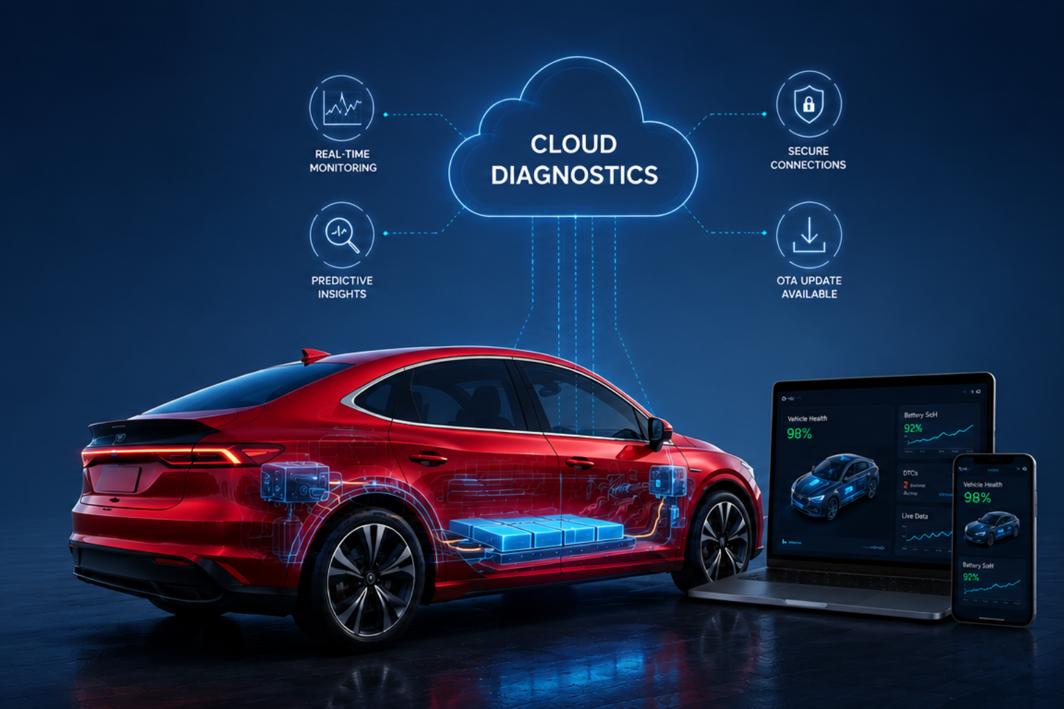
In this architecture, DoIP enables high-speed diagnostics, remote ECU programming, and parallel access to multiple ECUs, while gateway controllers transparently bridge Ethernet-based diagnostics to legacy CAN networks. This hybrid approach allows OEMs to modernize vehicle architectures without replacing every ECU simultaneously, making UDS a common diagnostic language across both traditional and next-generation platforms.
UDS for Electric Vehicles and AIS-189 Compliance
Standard ISO 14229 UDS covers general ECU diagnostics but does not define the EV-specific parameters that BMS, OBC, thermal management, and motor controller ECUs require. SAE J1979-3 (ZEVonUDS) extends UDS with EV-specific service parameters: battery SoH, SoC, cell-level imbalance data, isolation resistance, thermal management status, and charging session diagnostics. ZEVonUDS is the diagnostic standard for EV ECUs and is increasingly referenced in OEM supplier requirements for Indian market programs.
India's AIS-189 (effective October 2025 for new vehicle types) mandates that OEMs implement a certified Cybersecurity Management System (CSMS) covering diagnostic session hardening. This means UDS Security Access must use HSM-executed seed-key algorithms, diagnostic sessions must implement brute-force lockout, and remote diagnostic channels (DoIP over telematics) must be protected with TLS and certificate-based authentication. Non-compliant UDS implementations are a type approval risk under AIS-189. For OEMs with European market ambitions, UNECE R155 imposes equivalent requirements.
ElectRay's ZEVonUDS Stack and UDS Stack are aligned with SAE J1979-3, AIS-189, and UNECE R155 requirements, providing production-ready EV diagnostic and cybersecurity-compliant implementations for Indian and export market programs.
Conclusion
UDS (ISO 14229) is the diagnostic foundation of modern automotive engineering. From ECU development and EOL testing through field service, OTA update validation, and AIS-189 post-production monitoring, every stage of the vehicle lifecycle depends on a correctly implemented, production-grade UDS stack. As vehicles become more software-defined, UDS implementations must evolve: supporting DoIP for Ethernet-based architectures, ZEVonUDS extensions for EV-specific parameters, HSM-backed security for AIS-189 compliance, and ODX-based configuration for diagnostic data portability. SOVD is the horizon for AUTOSAR Adaptive programs.
ElectRay's UDS Stack, ZEVonUDS Stack, OBDonUDS Stack, and Secure Flash Bootloader provide a complete, production-grade ISO 14229 diagnostic ecosystem for OEMs and Tier-1 suppliers across passenger EVs, commercial and motorcycle.
Frequently Asked Questions About UDS Diagnostics
What is the difference between UDS and OBD?
OBD-II (SAE J1979) is a regulatory emissions diagnostic standard accessible to any scan tool through the standard OBD port. UDS (ISO 14229) is the full engineering diagnostic protocol used by OEMs and suppliers for development, EOL testing, service, and OTA updates. OBD covers only emission-related parameters; UDS covers all ECU functions. From 2027, US vehicles must implement OBDonUDS (SAE J1979-2), which runs OBD emissions diagnostics on top of the UDS architecture.
What transport layers does UDS support?
UDS (ISO 14229) is transport-layer independent. It operates over CAN via ISO-TP (ISO 15765-2), over Automotive Ethernet via DoIP (ISO 13400), over LIN (ISO 17987), and over FlexRay (ISO 17458). In modern SDV platforms, DoIP over Automotive Ethernet is becoming the primary diagnostic transport due to its higher bandwidth, parallel ECU access, and native IP addressability for remote diagnostics.
What is a UDS Negative Response Code (NRC)?
An NRC is a one-byte value returned by the ECU when it cannot process a UDS request. The negative response message format is 0x7F (negative response SID) + original request SID + NRC byte. Common NRCs include 0x22 (conditionsNotCorrect: ECU pre-conditions not met), 0x31 (requestOutOfRange: DID or parameter not supported in active session), 0x35 (invalidKey: wrong seed-key response), and 0x36 (exceededNumberOfAttempts: security lockout activated). See the NRC table above for the complete reference.
What is the difference between UDS and SOVD?
UDS (ISO 14229) is the established diagnostic protocol for AUTOSAR Classic ECUs, using binary service requests over CAN or DoIP. SOVD (Service-Oriented Vehicle Diagnostics) is the next-generation framework for AUTOSAR Adaptive platforms, using RESTful API calls over Ethernet for diagnostic access. SOVD enables cloud-native and remote diagnostic integration without requiring a UDS gateway. Both protocols will coexist during the SDV transition period as AUTOSAR Classic and Adaptive architectures run in parallel within the same vehicle.